
A Web Log of the K1 Rebreather Project
Prototype Development Log
Last Update 6/23/2006
NOTE: If you did not read the WARNING page, go back and do it now!
This is not the free rebreather resource page! If you came here looking for that, you clicked the wrong link. Go here!
All material on this page is Copyright (C) 2006/2007 Cuda Systems LLC and Karl Denninger. All Rights Reserved.
This page exists as a running "web log" of the K1 Prototype development.
What's the difference between this and the "freeware" page? Plenty. There are some shared attributes, but there are also important differences. One of the differences is that the prototype development has the potential to lead to a commercial product release.
Why would I make a web log out of this instead of just building it and then showing up on the market? Several reasons:
- I believe that there is far too much "mystery" involved in these things. Rebreathers are actually very simple devices. In fact, they're the earliest form of known diving device, predating open-circuit scuba by quite a bit. There's nothing particularly complicated about them.
- They tend to be very expensive when purchased on the open market. Some of this is justified, but not all. Justification for higher costs that comes from limited production runs is real, but justification thae comes down to "we'll sell 'em for whatever we can get by trading on the mystique" is unreasonable. This page is intended to dispell some of the mystique.
- If you understand how they work, you are less likely to be afraid of them. The other side of this is that hopefully you will think through some of the ways you can kill yourself with one of these devices. There are more ways to die than there are on open circuit scuba, but there are advantages to rebreathers as well. One of the big advantages is vastly-greater "duration" - that is, the amount of time before you run out of supplies underwater and die - compared to regular scuba tanks. Of course this assumes everything is working correctly....
Theory of Operation
When we breathe on the surface, we take in a mixture of oxygen (21%) and nitrogen (79%) (plus other trace gases). Our body consumes some of the oxygen (dropping the exhaled O2 content to about 16%) and adds in some carbon dioxide (~5%). Since we usually breathe out and in to the atmosphere with a basically unlimited supply of fresh air, this presents no problem.
On regular scuba equipment, we breathe in the same mixture (assuming we're breathing air) and exhale into the water. The same rule applies, except that since we brought the air with us, when its gone, we better be back on the surface "or else!"
A rebreather works a bit differently. You inhale, consume the oxygen and add the carbon dioxide, then exhale. The exhaled gas is passed through a chemical that reacts with the carbon dioxide and removes it from the gas. Then, using some mechanism, you must replace the oxygen you consumed. There are multiple ways of accomplishing this, from simply adding more gas to the system slowly from a supply tank (known as a "passive addition SCR"), to adding only oxygen slowly (or manually), known as a "manual CCR", to having electronics monitor the O2 content and add it automatically using some from of electrically-actuated valve (known as an eCCR).
The K1 is the latter - an eCCR.
Now from this there are some obvious potential problems. When on regular open circuit scuba gear, if you can breathe at all, you probably (absent a mixup with what's in your tank, or contamination of the gas) breathing something that will keep you alive. This is quite clearly not true on a rebreather, and is how people get killed using them, generally speaking. The following things can go wrong:
- You can happily breathe a gas that has absolutely no oxygen in it at all! If you breathe the oxygen content down below about 11%, you will pass out. Underwater, this is obviously bad, and is shortly followed by drowning.
- You can, due to error or malfunction, have the oxygen content rise too high. For depths below 20', it is possible to raise the oxygen content high enough that you will have what amounts to a "grand mal" epileptic seizure (caused by the excess O2) underwater. Of course this too is very bad, since losing control of your mental faculties usually causes you to spit out the mouthpiece - you subsequently inhale water and drown.
- The scrubbing system can fail, either due to getting too wet (water getting into the system), due to improper packing (known as "channeling"), the gas could bypass it due to improper assembly (you left a seal out or had one get damaged so the gas can go around the scrubber) or you can simply forget to either fill the scrubber or dive it beyond its useful life, exhausting it. Any of these will lead to the CO2 percentage going too high. That will cause nausea, headaches and can, with or without warning, result in unconciousness. Again, underwater, "falling asleep" is very bad since you will lose your mouthpiece, inhale water, and well, you know what's next.
- All the usual things that can go wrong when diving can still "get" you. That is, embolisms, decompression illness, etc.
What you trade off for this is no exhaust bubbles and far greater duration. The latter can be very important. Many people have died inside wrecks or caves because they ran out of breathing gas. In some cases they ran out within sight of the exit! With a rebreather your duration is measured in hours rather than minutes. Thus, while using one adds some risks, it helps remove some others.
What Makes the K1 Different?
A few things:
- The controller is built from commodity parts. This results in a relatively low-cost device. It does come with one penalty, in that it is more power hungry than some competing "specialty" units. Is this a benefit or drawback? Tough to call. One benefit is that since the design uses a standard 4.5AH NiMH light can as its power source (with an E/O underwater pluggable power cord) you probably already have the charger and extra batteries are usable both in the unit and your dive light. It also means you have a "hard" power switch you can use to turn off the unit if you suspect a malfunction caused by stray electrical current where it doesn't belong.
- The handset is built entirely of "space-age" plastics. Why? Because they work, are impervious to sea water (unlike most metals) and are tough as nails.
- There is only one handset. Some will call this a bug. I call it a feature, because in my opinion you want a secondary and completely different means of monitoring your dive anyway. For me, this is a VR3 computer. For others it may be something like the Cochran or Hydrospace computers. Point being, there should always be two indpendant ways of knowing what's up with what you're breathing. If one company builds both, and makes a mistake, it is likely to infest both. Not good. Knowing what you're breathing is key to staying alive on a rebreather!
- Cost. Make no bones about it, this is an attempt to take a shot across the bow of the current marketplace. Will it be successful? Good question. I believe so, but if I fail, here will be the evidence. I simply believe that the selling prices of the current units out there place them out of reach of too many people, and that there's no good reason for that sort of price point for most units. We'll see.
- Politics. Yes, politics. Click right here for more on that. This isn't just a quest for profit (although I am the first to admit that there's a profit motive here.) Its also my way of shouting from the rafters that I personally believe the current political situation surrounding diving - including rebreathers - sucks. If you/ve ever watched "The Three Stooges" you know all about fingers-in-the-eye. That's what this project is - aimed directly at the diving industry.
Anyway, the basics of the design are:
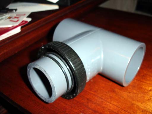
- Over-the-shoulder breathing bags. The original prototype will use MSR bags with modified caps. Before you groan, note that the late Gordon Smith used the same bags (and his company still does!) for the Classic KISS. Why? They're inexpensive and they work. If the prototype is successful, then I will work up commissioning custom breathing bags for a production run. The primary complaint I can see with the MSRs is that they have "edges" on the inside and out, and are a bit fatter and shorter than I'd like. We'll see how that translates in the water. The "T" pieces will, for the prototype, be made out of readily-available materials. If production goes forward, a commercial injection-molded T-piece will be produced.
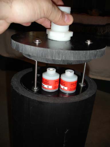
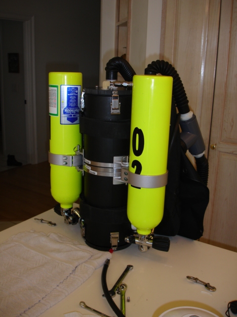
- The original design calls for a cross-shoulder cannister using the ExtendAIR cartridge inserts. The scrubber can is nothing more than a piece of pipe with fittings and end caps. The "head end" will contain the electronics (sensors, drive board and solenoid) while the "tail piece" is simply there to locate the cartridge in the proper place. An integral water trap is included in the cannister. A vertical cannister accepting loose absorbant is planned.
- The unit is designed to mount on a standard 11" center technical diving harness or backplate.
- The battery will be housed in a 12v 4.5AH light can, with switch and E/O cord. The E/O cord makes the system impervious to water penetration from the scrubber downward towards the battery, as the cord is effectively interrupted. The switch on the can means you can shut off the electronics if necessary, even underwater.
- The processor keeps all vital data in NV or battery-backed memory (lithium coin cell), so that even if turned off underwater it does not "forget" calibration - nor that you were diving at the time. The processor itself contains a multi-tasking executive allowing monitoring to proceed even when you are in a menu function, and was chosen both for its power and rapid development environment. While the unit contains a very complete bottom timer, no attempt is made to provide onboard decompression information. This is a philosophical decision - you need two timing devices for any decompression dive anyway, so your "offboard" one may as well be your deco computer. In addition, there is no agreement among divers as to which algorythm for decompression to use. No matter what was implemented, someone would want something else. As such the decision was made to "punt"; this also keeps the cost of the processor complex reasonable.
- All vital data about the dive is always on the top-level screen. On that screen when underwater you always have the PO2 of all three cells, the setpoint, the dive time down to the second, and any alarms posted by the controller. The backlight flashes for alarm conditions and is always lit at a very low level otherwise; on a night dive it is not necessary to press the button to "wake up" the backlight to simply have a look at things. The design calls for an annunciation device for alarms as well.
- Calibration is done in free air. You must also validate high setpoint operation (over 0.5) before the system will permit you to dive it. This prevents attempting to dive a setpoint that the O2 cells cannot register. Calibration is good for one day, while validation is good for one calendar week. If you insist on diving when the unit wants to be calibrated it will override the calibration demand when it reaches about 3' and go into dive mode, although obviously this is not recommended.
- The unit has one handset. Your second handset is presumably your decompression computer. It is strongly recommended that you use a 4th cell for the decompression computer so you have a completely independant means of reading the loop PO2 that relies on none of the unit's electronics.
- The prototype will not have an ADV, relying instead of manual addition. An ADV may be added in the future.
- O2 intermediate pressure will be set intentionally very low, in order to mitigate the risk of PO2 runaway if a manual add or solenoid is to stick open. In addition there will be a restrictor fitting on the O2 addition ports to further protect against this possibility.
- Water dumps will be fittred in both breathing bags; one will be of an automatic (e.g. "dry suit") style to permit relatively easy clearing of a partially flooded loop.
Status updates:
Software code is running; here are some screen shots:
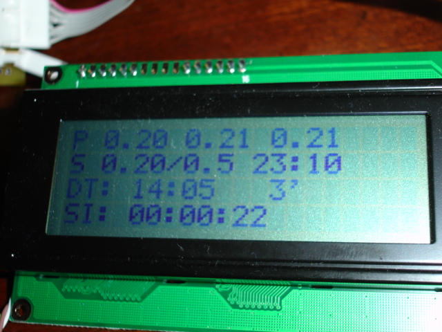
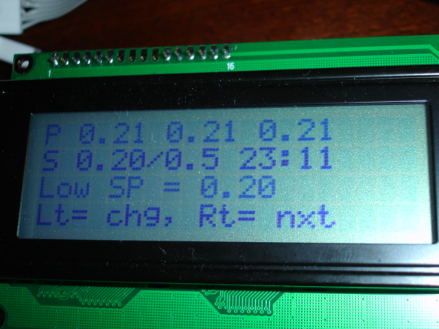
Here is your top-level screen when on the surface. The top line are your three cells (all are within tolerance); the next is the setpoint and validated point, followed by the current clock time. Dive time is below (last dive), which had a max depth of 3' for 14:05 (ok, it was a long test!) Below that is your surface interval. When the SI reaches 12 hours the dive time is blanked and your SI is considered to have reset.
If you were diving the "DT" line would have seconds in it and the feet indicator would be to the far rght. Note the right side of the display - the entire 4 character right set (4 lines) is reserved for alarms.
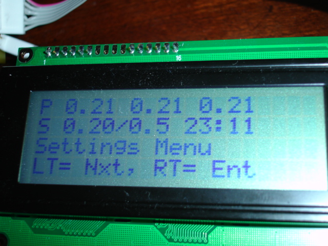
One click left brings up the menu system. Each additional click at the menu level advances, right enters the menu you are pointing at. Time and PO2 continue to update while in the menus.
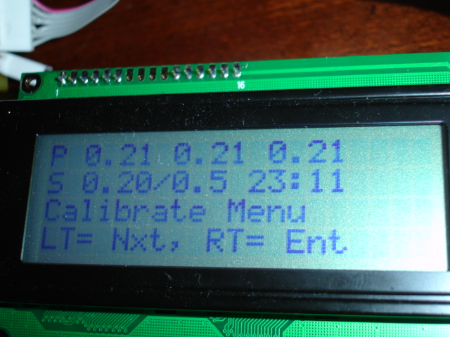
The Calibrate menu selector....
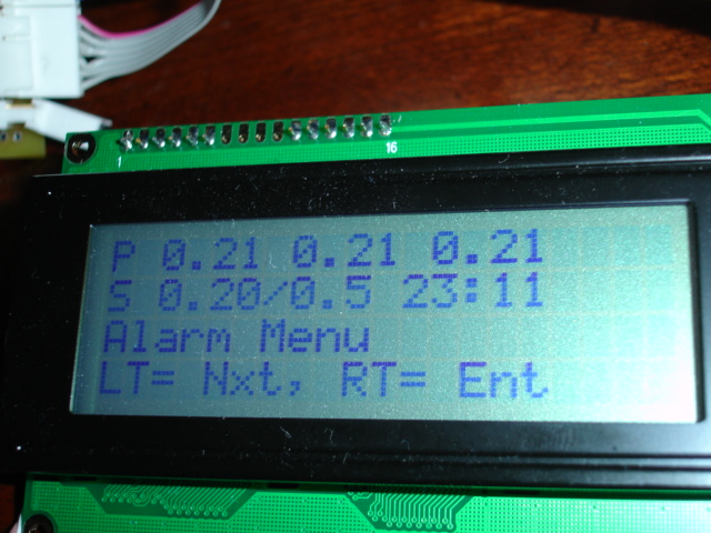
To view alarms.... (note that there are none right now)

The millivolt, battery, and millibar display. The millibar display only comes up on the surface. The pressure sensor is only accurate to about 10mb, so this isn't terribly accurate, but it does tell you what's going on with that part of the system. The millivolt sensor levels are important if you suspect trouble of some kind, and the V+ battery rail is also useful. We are currently running off a 5 AA NiMH battery pack - the actual prototype unit will run off a 12V NiMH pack. Low voltage warning level for the 5 AA pack is at 6VDC. The voltage display is accurate to within .02V over its full range, and you can actually see it change when the backlight comes on or the solenoid fires..
The low setpoint modification off the settings menu. Note that now you must press LEFT to change the setting, or right to go to the next function. This is because you pressed RIGHT to get into here - we always alternate buttons to avoid accidentally confirming a change you didn't mean to make. Also, any time you leave all buttons alone for 10 seconds, you are returned to the top-level diving display.
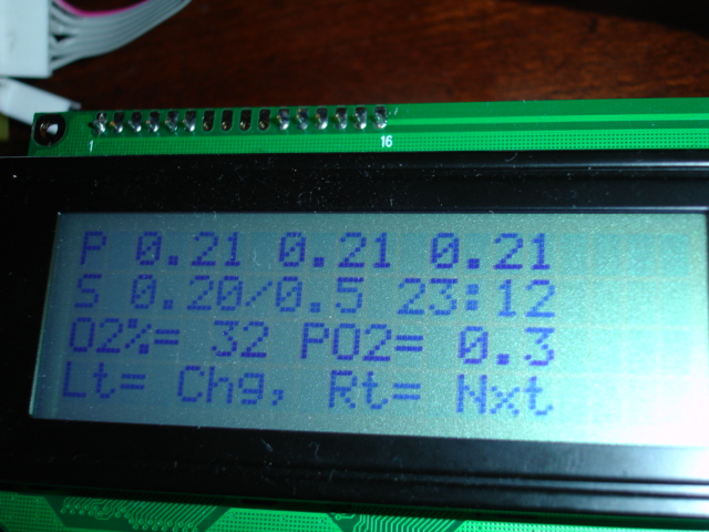
The PO2 informational display. If you set the FO2 of your diluent here this screen will tell you what the PO2 should be for a diluent flush at the present depth. This is very useful and avoids having to "do math" at depth if you suspect your equipment is not giving you the right information. Set the FO2 here before you go diving, and at any time you can do a diluent flush and ascertain if the sensors are completely out of whack or not. Of course since we are currently on the surface the PO2 is equal to the FO2.....
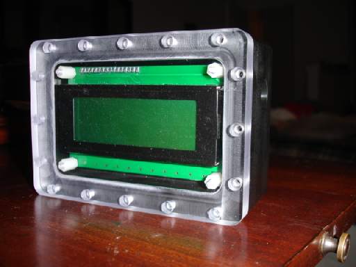
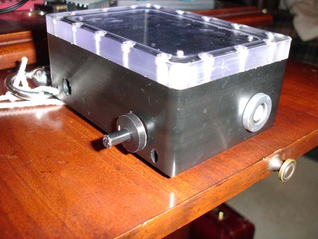
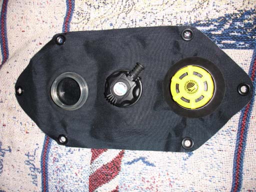
The completed handset case with a LCD mounted in it (the Fischer connectors are not yet here....)
Some torture test results....
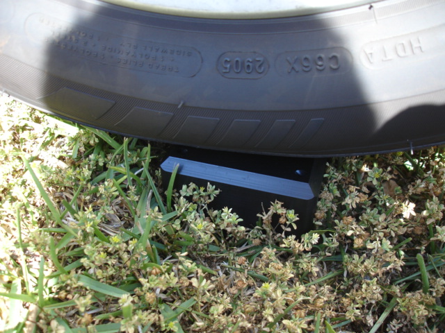
Car .vs. Handset, face down; weight of the vehicle (this tire's weight anyway) entirely off the ground and on the handset: PASS
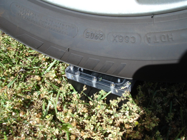
Car .vs. handset, FACE UP, entirely off the ground (on the weakest part.) PASS - and note the O-ring seal is still clearly visible (no leakie!)
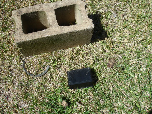
We know how nice open circuit divers are, so I figured that dropping a cinder block from a height of 8' (on a ladder) on top of the handset might be a good impact test. This is after about half a dozen such drops - Result: PASS
Not bad!
Here is the handset with the buttons installed (loosely so you can see how they screw in) The buttons were made on a MicroMark mini-lathe out of delrin rod, and are backed with a SS spring. The magnet is epoxied into a small hole drilled in the end of the shaft. The only exposed metal is the SS spring, eliminating dissimilar metal corrosion concerns in sea water. The entire button assembly is designed to be replaced using nothing more than a pair of pliers (if they get stuck and won't come out by hand - they should!) inside of 30 seconds if required (e.g. you bash one badly enough so that the stalk is fouled and won't work right any more.) The stalk and surround are both made out of turned Delrin, and should survive fairly severe abuse.
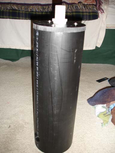
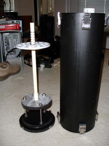
For the cannister I am now intending to use a coaxial "loose pack" cannister, made out of 6" DR11 HPDE pipe. The cannister design has undergone a couple of changes; I have binned the downtube coaxial design, primarily due to problems with figuring out how to accurately insure that the scrubber head mates with the down tube. So for the first incantation it'll be a straight axial scrubber with a side inlet and the downtube on the outside. This also frees up the inside of the can significantly, allowing me to eithe carry more 'sorb or use a somewhat shorter can. The ExtendAir option was binned when I realized that mounting on a standard backplate actually required a LONGER cannister in order to have the unit rest on its scrubber when on a boat (desireable), and that getting all the pieces in the head for the original design, while possible, was NOT going to be easy.
Here's the can and head - the head (and bottom pieces) are each made of 2 pieces of 1/2" Delrin, concentrically mounted. The head's through-bolts are O-ring sealed at the top and clamp the two pieces together in the proper relationship. The seal is made with a crush O-ring, much like a Gavin or SS scooter, as the surface of the tube is not round enough to use a barrel ring.
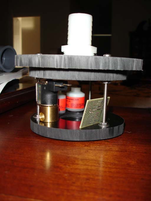
The head assembly picture shows two (of four possible) sensors mounted - three for the controller and one extra for a VR3 or similar. The solenoid and signal board are not mounted but shown to give scale and size. Its not particularly crowded, but is somewhat "busy". The design is such that you can change the O2 sensors without having to disassemble the head carriage; there is sufficient clearance and "finger space". The solenoid will bolt down to the bottom carriage as shown (but the alignment is all off); the head board itself will be encapsulated. The through-lid cable glands are obviously not yet installed.
Finally, here's a picture of how the head looks when "half inside" the can. The can (after the edge is finished to an acceptable level) will have Nielsen Sessions latches mounted (three) for closure.
The T-pieces are 1-1/2" Sch 80 PVC, which happen to fit a modified MSR water bag quite nicely with a bit of machining.
The scrubber, of course, requires scrims to hold the 'sorb in place. Since we're using a direct-pack scrubber (that is, there is no "inside can") the bottom for the cannister also has the bottom scrim attached, along with the location / tamping rod. The tamping rod is 1/2" CPVC; it is simply there as a guide and to give the top scrim something to ride on and retain the spring and clip.
The bottom assembly should be up in pictures here shortly - in the meantime, here's the scrim itself for the top
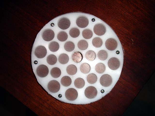
The actual body is made of 1/4" PE plastic; it is nearly 100% inert, including against caustics (which the scrubber media is!) The scrim material itself is a very fine polyethylene mesh - its extremely strong yet will not permit pieces of 'Sorb to pass. This is the actual top piece that will sot on top of the scrubber media - directly under it will be a fiber pad (to control dust migration towards the inhale side.) The pad itself has zero integrity in terms of structure, so we use this. The mesh is secured with six stainless steel screws and thus is easily replaced if damaged; it was obtained from http://www.smallparts.com and cut to fit. The frame has a pattern of 5/8 and 3/4" holes drilled so as to permit gas to pass; the center hole is for the 1/2" CPVC guide rail. Note that producing this piece requires nothing more than a scroll saw and drill press, along with a sander to finish the edge to fit the tube tightly. A firm fit is essential to prevent 'Sorb from being able to come around the outside edge and since the scrubber pipe is not precisely round you cannot turn this on a lathe - you have to cut it rough and then use a stationary disc sander for fine contouring to fit. This also means the insert itself is directional (it only goes in the hole one way.)
In operation the fiber pad will be loaded, followed by the scrim (the face you see will be facing the absorbant in actual use.) Next a spring will be placed over the guide rail and a pin placed through it, applying pressure to the frame, thus helping to prevent channeling. There will be two "pin insertion" points in the can - one for a "full load" of 'Sorb, the other for roughly a "half load" which will be useful for times when you intend to make only two recreaitonal-depth and time dives in a day, and do not wish to waste a half-load of "rocks."
Here's the can, with latches and the insert - note that the top scrim is positioned on the rod, but in actual use you will load the cannister with sorb, then place the top scrim in from the top, put the spring on top, then put the pin in place. The pin hole location is not yet drilled as I have not yet determined exactly how much 'Sorb will be used for the two locations (this to come in the next couple of days.) The center rod goes nicely up the hole in the top of the lid and, in use, a cap is placed (friction fit) over it to prevent channeling between the two pin locations out (allowing un-scrubbed or partially-scrubbed gas to bypass.) Cannister airtight integrity has been tested - no problem - the Nielsen Sessions latches were set for 70lbs of force at installation.
Buildup pictures - front and rear (still in process....)
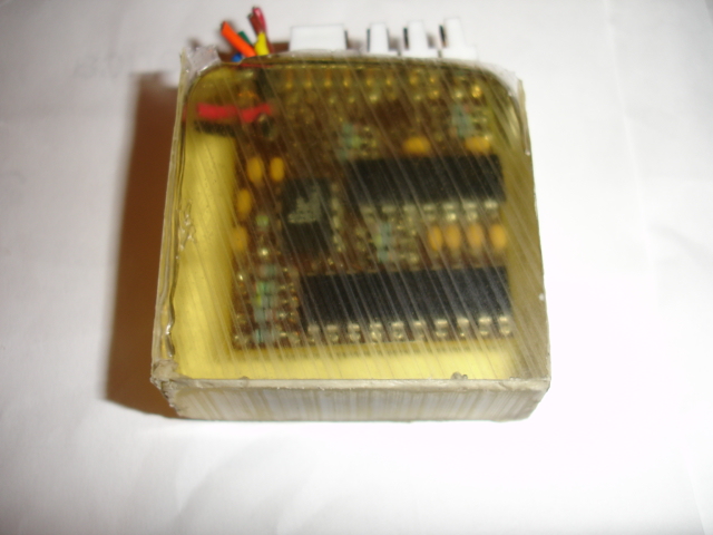
Here's a "test shot" of the potted headboard, using a dead one of course. Totally encased in de-gassed (under a pulled vacuum) epoxy casting, except for the sensor connectors at top. Not bad, not bad....
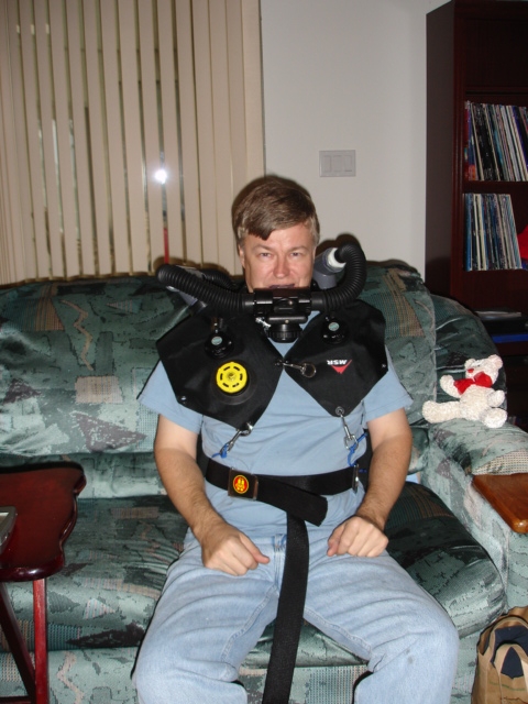
Couch Dive! All on manual as an O2 rebreather, no controller in the loop yet.
Scrubber scrubs - watched "X-Men" through to the end on the loop, along with about 10 minutes on the stationary bike. The gas gets uncomfortably HOT on the bike.... no cooling from the water, and level of work has gone way up of course..... Still here - must be working reasonably well :)
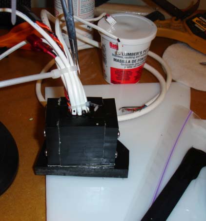
Potting up the head board for final assembly...... (its all here and going in now!) Using a mold make out of Delrin sheet screwed together, with mold release sprayed inside (epoxy doesn't stick well to Delrin, but it still requires more wokr than you'd like without the mold release to get it apart later.... the spray makes it easy.)
Latest - the head board and solenoid integration is complete, and bench tuning of the injection algorythm has been performed. All looks good. Pool dives tomorrow (11/6), with luck - I've also come up with the "half-pack" cannister option so that I can use half loads for the pool and shallow water dive testing.
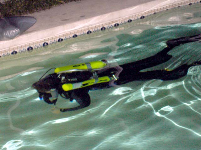
Look ma, no bubbles!
June 2007 - Updates!
After plenty of diving I got really bothered by the T-pieces. So I decided to do something about them - and went back to the lathe and drill press. Ordering up a heat gun, I fashioned the following out of a piece of HDPE solid, a piece of HDPE pipe, and a small piece of sheet to make the divider in the "T". These are much smaller and lighter than the plumbing parts, and are MUCH more comfortable. Note the "relief holes" drilled at 90 degree angles to the divider to insure that the gas path never gets obstructed.
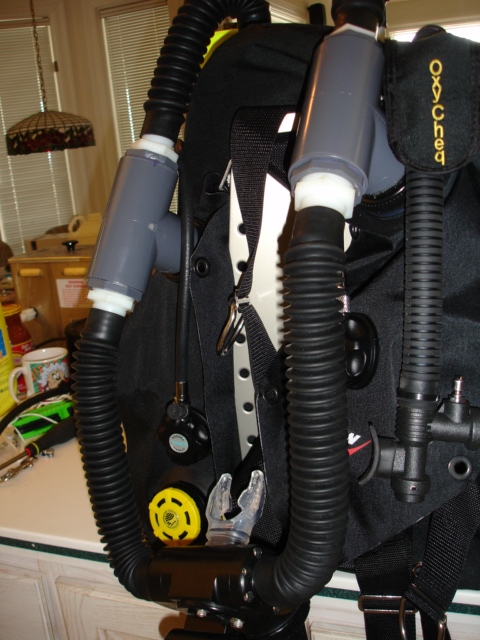
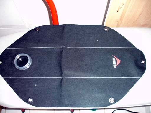
Next up were the counterlungs. The MSR bags work, but they're not great in stock form. The problem is that they're both too short and fat, and bunch up at the top as a consequence along with rubbing on your neck. Not hard to solve - it turns out that the MSR bags can be field welded using nothing more than an ordinary iron! So I ordered up some 10L bags and modified them. We start by laying out the seal lines for the modified bag - the shape we want when we're done, like this:
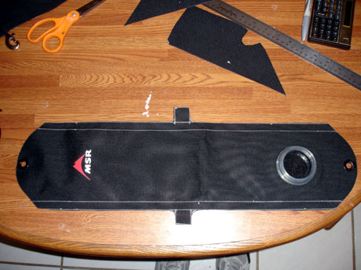
Now, using an ordinary iron set to LINEN (maximum heat, dry) we iron the seam lines, moving the iron VERY SLOWLY with VERY FIRM pressure to insure that sufficient heat is applied. The urethane heat-welds to itself along the line. Make sure that you have at least a 1/2" seal line; 1" is better.
Then draw a second line leaving a 1/2" seam. At the halfway point create a 1x1" tab to which you can later sew hook and loop (velcro) so you have a means to secure the center of the counterlung to your backplate harness. Round the corners so you don't create a "hardpoint" which will tear. When you're done you have something that looks like this:
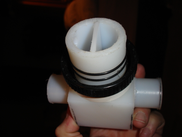
Now locate your manual add valve (this is for the inhale bag, so there is no OPV - that is on the exhale bag), draw the port, cut it, insert the backing nut through the inlet (note that this is VERY DIFFICULT - you have to pinch the T-piece attachment port which is HEAVY - but pliable - plastic, then force the nut through), position the valve port, backing nylon and valve, and screw it down.
The lung, needing only the strapping for securement to the harness, inflated (with the original cap) to test for airtightness, looks like this:
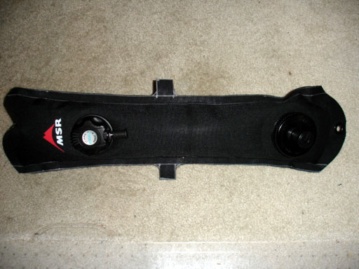
It snaps on the harness as does the original, using bolt snaps on the top and bottom. The velcro webbing to allow it to be secured to the diver's shoulder straps is then sewn into the tabs and the lung is complete.
Questions? Feel free to ask away by email!
If your mail bounces you get to try to pass the Turing Test (another name for a test of sentience - if you can't pass it then you probably should be playing with dangerous toys like Rebreather Controllers!)
Enjoy, and dive safely!
Current Project Status:
| Start Date | Expected Complete | Completed | Milestone |
|---|---|---|---|
| 12/1/2005 | 12/20/2005 | BS2pe code breadboard operational w/code | |
| 12/21/2005 | 1/9/2006 | PC Boards cut, filled and working | |
| 1/10/2006 | --- | --- | ZX controller code begun development |
| 2/15/2006 | 3/31/2006 | Cut purchase order for handset cases and Fischer Connectors | |
| 2/27/2006 | --- | --- | First release of public web page |
| --- | --- | 3/17/2006 | Receive handset cases from machine shop, begin integration |
| 3/17/2006 | --- | --- | Add K1 prototype and policy/politics page |
| 4/4/2006 | 4/20/2006 | 4/8/2006 | R3.0 controller board layout begins |
| 4/4/2006 | --- | --- | Ordered mini-lathe to be able to make "fiddly bits" required for the remaining assemblies. |
| 4/8/2006 | --- | 4/13/2006 | R3.0 controller boards out for fabrication |
| 4/10/2006 | 4/10/2006 | First round of handset torture tests performed. Result: PASS | |
| 5/1/2006 | Hiatus - travelling with my kid :) | ||
| 8/4/2006 | Back at it...... electronics R3.1 sent out to be made; 4-layer board for head and revision to the solenoid driver for the CPU | ||
| 8/25/2006 | Preliminary verification of the R3.1 boards complete - one minor revision required for 3.2 in the CPU board, but not fatal to the operation of the unit as it stands. Scrubber pipe ordered for a coaxial, loose-pack unit (vertical mount) | ||
| 9/11/2006 | Buttons complete on handset, T-piece design complete, scrubber build-up in process | ||
| 10/2/2006 | Scrubber can almost complete, counterlungs compelte, build-up commences | ||
| 11/5/06 | Build-up compelte, including electronics integration. Into the water she goes! | ||
| 6/06 | OW diving continues. Two issues identified - counterlungs a PITA due to shape (fixed, see above) and a depth sensor problem has been identified. A fix is under investigation; if that (sealing the back) fails then I will be forced to redesign the electronics to move them entirely outboard, as the depth sensor will have to have its "rear" in a 1 ATA space. This will lead to a minor change in the head (with reduction in volume - good for buoyancy) but also necessitate new handset cases and a new electronics case - bummer if necessary. Testing continues. |